A car camera is a small box glued or bolted to a moving machine. Every pothole, door slam and car wash nudges it. A nudge of one degree is invisible to the eye, but it is enough to put a parking guide line or a distance estimate in the wrong place.
The usual answer is to measure the camera once, in the factory, against printed targets. The question this post is about is harder: how can a camera find out on its own, while the car is being driven on an ordinary road, which way it is really pointing?
At ADASENS Automotive, a FICOSA subsidiary, I worked on exactly that problem; the patent application was filed in February 2018. Together with David Hafner and Sebastian Carreño, I am named as an inventor on the resulting patent, Calibrating a camera of a vehicle (EP3531376B1). This post explains its idea without a single equation. If you can picture looking out of a train window, you can follow it.
A note on what is mine and what is the patent’s. The method below is described in the published patent, and I stick to what it says. The analogies and the opinions at the end are my own.
Why a camera needs calibrating at all
A camera only sees pixels. To turn “the kerb is at pixel 412” into “the kerb is 1.8 metres behind the bumper”, the software must know exactly where the camera sits and which way it points. Engineers call that knowledge the camera’s calibration. The part this patent is about is the pointing direction, usually described by three angles:
- Pitch: is the camera tilted up or down?
- Yaw: is it turned to the left or right?
- Roll: is the picture rotated, like a crooked photo frame?
Small angles matter. A one-degree error shifts a point 10 metres away by about 17 centimetres, and a point 30 metres away by about half a metre. That is the difference between a parking line that fits the bay and one that does not, or between an obstacle in your lane and one next to it.
The factory measures these angles at the end of the assembly line, with targets placed at known distances. As the patent points out, that does not solve the problem in the field. Manufacturing tolerances, vibration from bumpy roads, door slams, car washes, repairs, replaced parts and folding mirror housings can all move the camera over the life of the car. Nobody wants to drive back to the factory, or to a workshop with calibration boards, every time that happens.
So the camera has to work it out by itself, from whatever happens to be in front of it.
Clue 1: the point the world streams from
Think of driving through snow at night. The flakes in your headlights seem to burst out of one spot straight ahead and fly past on every side. Or think of the “jump to hyperspace” in a science-fiction film, where the stars stretch into lines that all start from the same point.
The same thing happens with an ordinary road, only more slowly. The software picks small, recognisable spots in the picture: a crack in the asphalt, the corner of a road marking, a speck of gravel. It follows each spot from one video frame to the next. Joined up, each track becomes a short arrow that shows how that spot moved across the picture. The patent calls these arrows flow vectors.
When the car drives straight ahead, all those arrows line up on lines that meet in one point. That point is where the car is heading. For a rear-view camera, it is where the car is coming from, and the road streams into it instead of out of it, but the geometry is the same. The patent calls it the focus of expansion and uses the term interchangeably with the vanishing point: the place where parallel lines, like the two edges of a long straight road, seem to meet.
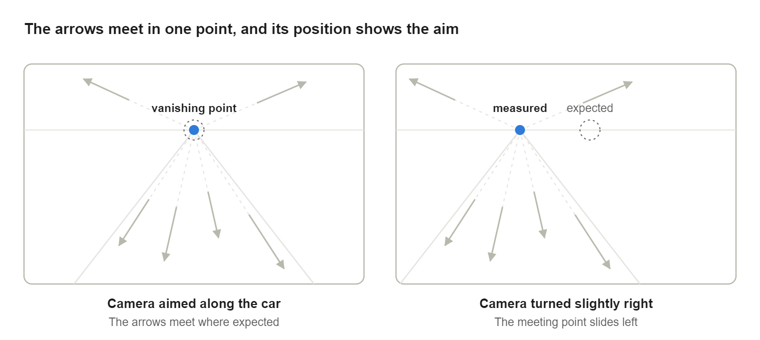
Here is the useful part. That point marks the car’s direction of travel, and the car drives forwards, along its own length. So wherever the vanishing point appears in the picture tells the camera where “straight along the car” is, seen from its own point of view:
- If the camera points exactly along the car, the point sits where the designers expected it.
- If the camera is turned slightly to one side, the point slides sideways in the picture.
- If it is tilted down, the point slides up, and the other way round.
The first clue, then, is forward: one direction, measured purely from how the road moves.
Clue 2: the way the road moves
Forward alone is not enough. A camera could point perfectly along the car and still be rolled like a crooked picture frame. The second clue comes from the road surface itself.
Stand at a train window and look down at the platform as the train pulls out. The paving stones close to you rush past; the ones further away drift slowly. That difference in speed across your view is not random. It depends on how the platform is tilted relative to your eyes. Tilt your head, and the pattern of fast and slow tilts with it.
The patent uses the same effect. It marks a patch of the picture where the road surface normally is, just behind or in front of the car, and calls it the ground plane mask. It takes the arrows of spots inside that patch, at least three of them, because three points are the minimum that pin down a flat surface. A flat surface moving past a camera makes its points move in a very regular way, and that regularity, together with how the camera itself moved between the two frames, reveals how the surface is oriented.
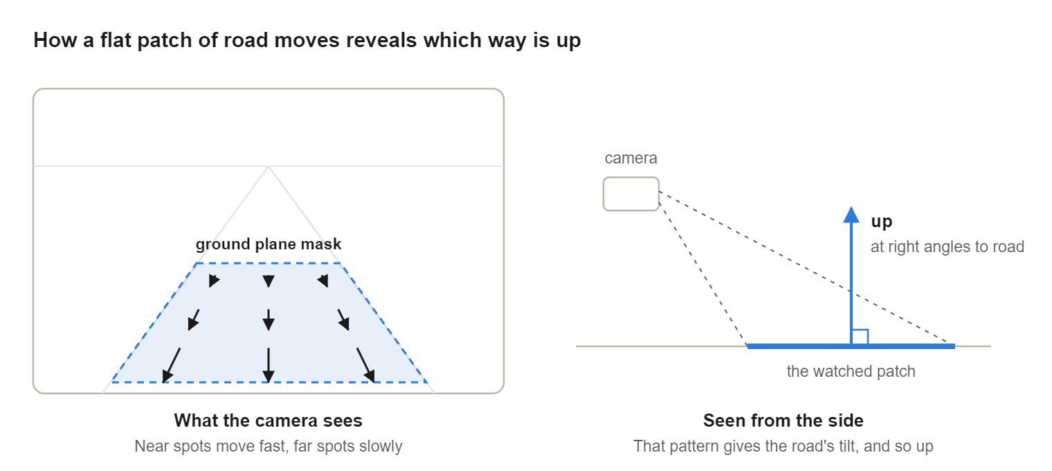
The result is the direction that stands straight up out of the road, at right angles to it. Mathematicians call it the normal of the plane. In everyday words, it is the camera’s sense of up.
Notice what the method does not need: no lane markings, no kerbs, no special signs. Any road with a bit of texture will do.
Putting it together: forward, up, and the third for free
Stand in the corner of a room. The floor and two walls meet at right angles, and three edges run away from your feet: one ahead, one to the side, one straight up. If you know two of those directions, the third has no choice; it must be at right angles to both.
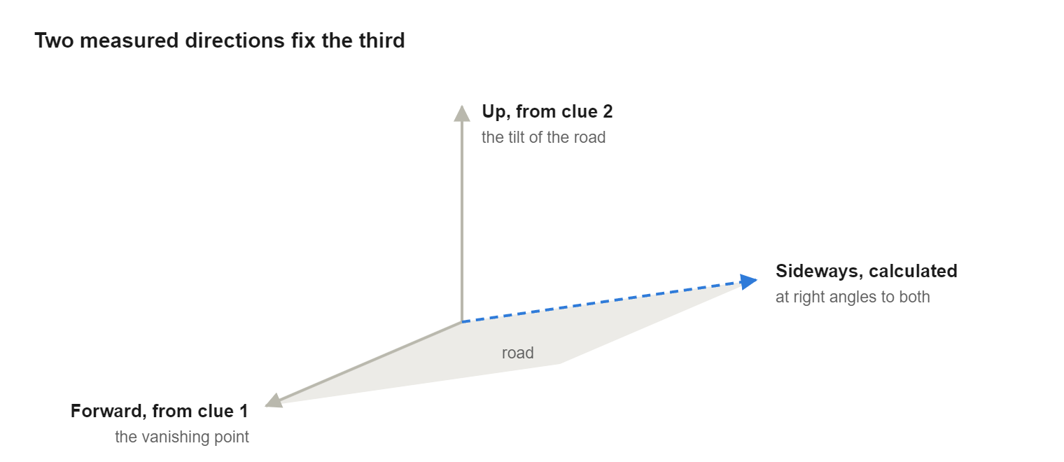
That is the heart of the patent. The camera now knows two directions in its own view:
- Forward, from the vanishing point (clue 1).
- Up, from the tilt of the road (clue 2).
- Sideways is then calculated as the direction at right angles to both. In the patent this is a single step, a so-called cross product.
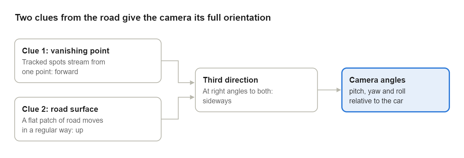
Together, those three directions describe completely how the camera is turned relative to the car. The patent stores them as the three columns of a small table of numbers, the camera calibration matrix. From that table, the familiar three angles, pitch, yaw and roll, follow directly.
Real measurements are never perfect, so the measured forward and up may come out not quite at right angles. The patent handles this simply: it nudges the up direction until it is exactly at right angles to forward, then completes the set.
Why is this a neat idea? Each clue on its own is incomplete. The vanishing point says nothing about roll; the road surface alone says nothing about where along it the car is heading. Combined, they leave no gap.
Being picky: good measurements only
The idea fits on a napkin. Making it reliable on real roads is mostly about knowing which measurements to throw away. The patent describes several filters.
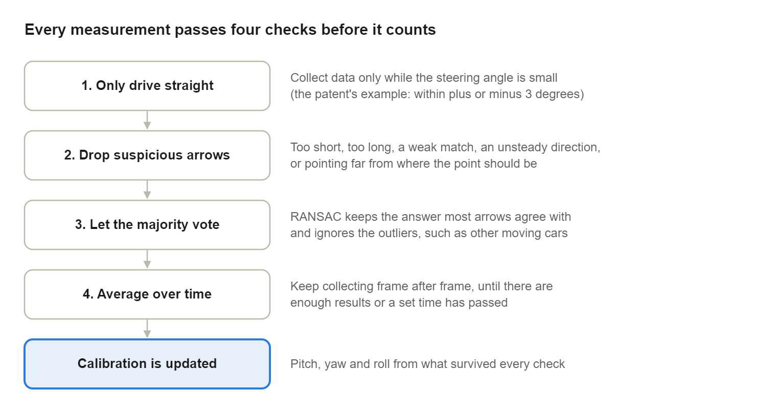
Only drive straight. The vanishing-point trick assumes the car is moving straight ahead. In a bend, the arrows curve and the point wanders. So the system reads the steering angle from the car’s network and only collects data while it is small; the patent gives ±3 degrees as an example. In town that may be a few seconds at a time. On a motorway it is most of the trip.
Distrust suspicious arrows. An arrow can be wrong because the software matched two spots that were not really the same. The patent rejects arrows that:
- are too short to show a clear direction, or so long that they are probably a mismatch;
- come from a weak match between frames;
- change direction from frame to frame, when a real spot should move steadily;
- point far away from where the vanishing point is expected to be, given that the camera was mounted within a few degrees of its design position.
Let the majority vote. Even after filtering, some arrows are wrong, for example from another moving car. The patent uses a well-known technique called RANSAC: try many small groups of arrows, see which answer most of the others agree with, and ignore the rest. It is like asking a room of people the time and ignoring the two whose watches are clearly broken.
Average over time. The system keeps collecting vanishing points and road directions, frame after frame, and averages them. It only produces a calibration once it has enough of them, or after a set time. To keep within the limited computing power of a car camera, the heavy work can be spread across several frames.
Mirror-image cameras. Some cameras replace a mirror, so the picture shown to the driver is flipped left to right. The patent simply flips the arrows back before doing the geometry, so the same method works.
What makes it different, and where it stops
The patent compares itself with two earlier families of online calibration. Methods that rely on road markings only work where there are clear lines to see. Methods that rely on features on the road are more flexible but, as the patent puts it, prone to errors because the road is not always flat where they assume it is.
Against that background, the patent claims three practical advantages:
- No road markings or special features are needed. Ordinary texture on the asphalt is enough.
- No second sensor. It works with the single camera being calibrated; no second camera and no lidar.
- No exact starting value. The patent states that no prior knowledge of the camera’s initial position is needed to calibrate it. One of the optional filters does use the rough assumption that the camera is within a few degrees of its design position, which is a safe assumption for a camera bolted to a car.
It is just as important to say what the method does not do:
- It needs the car to move, and to move fairly straight. A parked car, or a car on a winding mountain road, gives it little to work with.
- It needs something to track. A road with visible texture is fine. Fresh snow, standing water or deep darkness give the camera far fewer reliable spots.
- It still assumes a flat patch of road. Averaging and the majority vote reduce the damage from a bump or a camber, but they do not remove the assumption.
- It measures where the camera points, not the lens. Properties of the lens itself, such as its focal length and centre, are taken as known from the factory. They do not drift the way a mounting does.
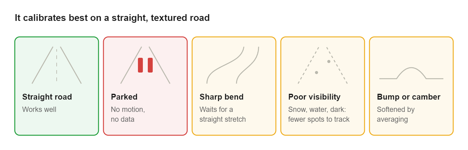
None of this is a weakness of the idea so much as the honest shape of the problem. A camera cannot learn its orientation from a picture that does not move.
From patent to road
The European application was filed on 21 February 2018 by Ficosa Adas S.L.U. Applications in the US, Japan and China followed a year later, and all four have been granted:
| Office | Patent | Granted |
|---|---|---|
| Japan | JP7355505B2 | 3 October 2023 |
| China | CN110176038B | 10 December 2021 |
| United States | US10902641B2 | 26 January 2021 |
| Europe | EP3531376B1 | 30 September 2020 |
The algorithm behind it went into production as the online calibration for a rear-view camera system in the 2019 Audi e-tron. There is a short demonstration video of the calibration running on the road.
For me the satisfying part is not the certificate but the step from a formula on a whiteboard to code running on a small automotive processor, inside a car that strangers drive every day, quietly correcting itself after the next car wash.
What I take away
Calibration is a lifetime property. The factory measurement is only the first one. A camera on a car lives through years of vibration and repairs, so the system has to keep checking itself, the same way safety and security have to hold over a product’s whole life.
Use the motion you already have. The car moves anyway. Instead of treating that movement as a nuisance, the method turns it into the measuring instrument. Good engineering often looks like this: the signal was there all along.
Two incomplete clues can make a complete answer. Neither the vanishing point nor the road surface is enough on its own. Together, with one line of geometry to fill in the third direction, they are.
Most of the work is saying no. The core idea is short. Making it trustworthy meant deciding when not to measure, which arrows to throw away and when an answer is stable enough to use. That is where real-world robustness comes from, in calibration as in most software.
The next time a parking line on your screen fits the bay exactly, there may be a camera behind it that has quietly checked its own aim on the way there.
Sources
- David Hafner, Taner Güngör, Sebastian Carreño: EP3531376B1, Calibrating a camera of a vehicle, European Patent Office, granted 30 September 2020 (full description: EP3531376A1)
- US10902641B2, Methods of calibrating a camera of a vehicle and systems, granted 26 January 2021
- JP7355505B2 and CN110176038B, the Japanese and Chinese members of the family
- European Patent Office: bibliographic data and patent family for EP3531376B1
- Demonstration video of the online calibration
- Featured image: Alexandre Polounovsky, Unsplash (free to use under the Unsplash License)
- Figures: my own illustrations of the method described in the patent